


 Deutsch
 English
 Italiano
Fused Deposition Modeling (FDM): 3D Printing with Thermoplastic Filament
Fused Deposition Modeling (FDM) – also known as Fused Filament Fabrication (FFF) – is a 3D printing process from the material extrusion group: a plastic wire, the filament, is melted in a heated nozzle and deposited path by path onto a build platform. The strand solidifies and bonds with the layer below. This is how the part is built up layer by layer.
FDM plays to its strengths above all in two cases: when a specific material is required – for example flame-retardant, fiber-reinforced, electrically dissipative, elastic or for sliding applications – and when parts are larger. For industrial functional parts or parts where appearance matters, it is worth taking a look at laser sintering (SLS): it needs no support structures and shows no pronounced layer lines.
FDM at a glance
- Process principle
- Material extrusion: melted filament is deposited path by path
- Materials
- Thermoplastics, including flame-retardant, fiber-reinforced, conductive, elastic and sliding materials
- Support structures
- required for overhangs
- Surface
- Layer lines visible
- Part properties
- direction-dependent
- Quantity
- Single part to small batch
Guide values, not guaranteed properties. The information provided by the supplier in the ordering process or in the quote is authoritative.
How it works
How does FDM work?
Drive wheels feed the filament into a heated nozzle, where the plastic melts. The print head traces the contour and infill of the current layer and deposits the strand on the build platform or the previous layer. Once a layer is complete, the distance between nozzle and part increases by one layer thickness – and the next layer follows. Overhangs are supported by support structures during printing.
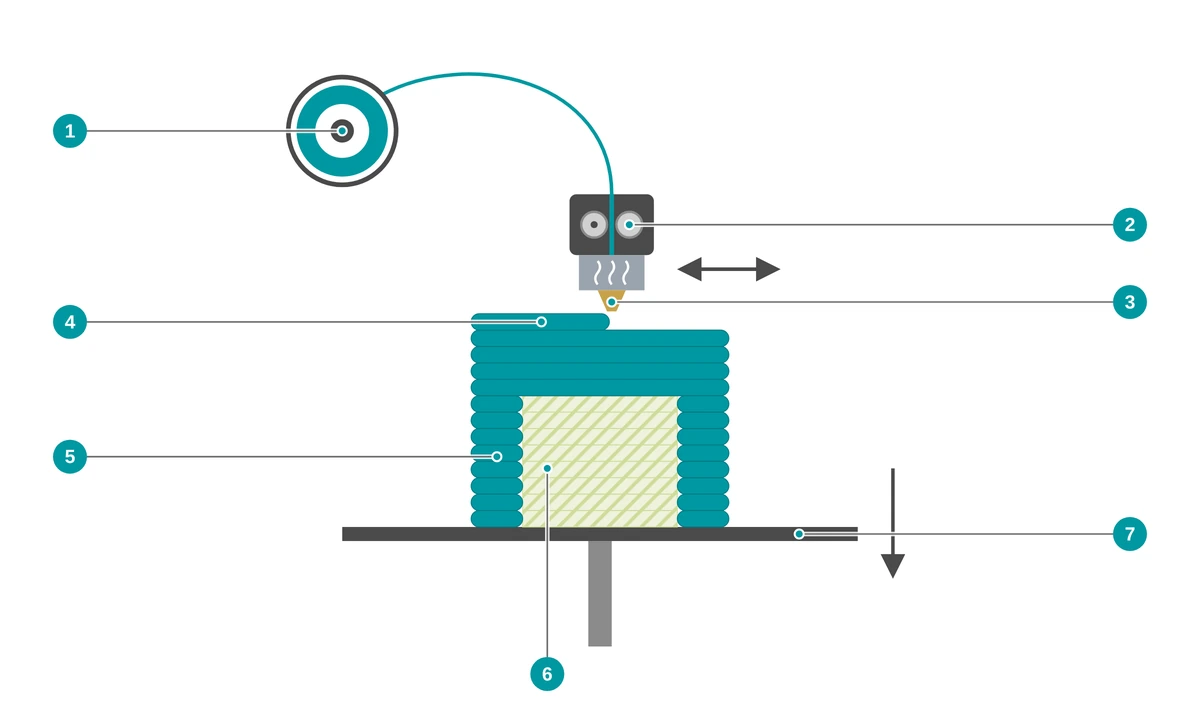
- 1 Filament spool with thermoplastic
- 2 Drive wheels feed the filament to the nozzle
- 3 Heated nozzle melts the plastic
- 4 Melted strand is deposited path by path
- 5 Part, built up layer by layer
- 6 Support structure under overhangs, removed after printing
- 7 Build platform – after each layer, the distance to the nozzle increases by one layer thickness
- Prepare data The 3D model is oriented and sliced into layers. The nozzle paths and – where necessary – support structures are calculated.
- Melt the filament The filament is fed to the heated nozzle and melted there.
- Deposit path by path The nozzle deposits the strand along the contour and the infill. It solidifies and bonds with the layer below.
- Layer by layer After each layer, the distance to the nozzle increases by one layer thickness until the part is complete.
- Remove supports After printing, support structures are removed – mechanically or, with some systems, by dissolving.
- Finishing Whether further finishing steps are possible depends on the supplier – you can see the available options in the configurator.
FDM or SLS?
What is the difference between FDM and laser sintering?
In FDM, a filament is melted and deposited as a strand; in laser sintering, a laser melts plastic powder. Laser sintering needs no support structures, is suitable for complex geometries and shows no pronounced layer lines – which makes it the obvious choice for many industrial plastic parts. FDM plays to its strengths with special materials and larger parts.
| FDM | Laser sintering (SLS) | |
|---|---|---|
| Starting material | Filament (plastic wire) | Plastic powder |
| Layer build-up | Nozzle deposits melted strand | Laser melts powder particles |
| Support structures | required for overhangs | none – the powder bed supports the part |
| Surface | visible layer lines | slightly rough and matte |
| Materials on the Marketplace | wide range of thermoplastics, including flame-retardant, fiber-reinforced, conductive, elastic | including polyamides, also electrically dissipative |
| Particularly useful | for special materials and larger parts | for industrial functional and visual parts, complex geometries and series |
Which process suits your part better depends on material, geometry, load, appearance, size and quantity. Upload your file and compare the offers directly in the configurator – or contact us.
↑ Back to overviewAdvantages
What are the advantages of FDM?
The strengths of FDM lie in the choice of materials – including flame-retardant, fiber-reinforced, conductive and elastic thermoplastics as well as sliding materials – and, depending on the machine, in larger part dimensions. Parts are created directly from the CAD data, without tooling.
Special materials
High-performance plastics such as PPS-CF10, PPA-CF and PVDF as well as materials with special functions.
Materials with UL 94 V-0
The materials ABS-FR, ABS/PC-FR, PETG V0, PPS-CF10 and PVDF are classified according to UL 94 V-0 – from the specified wall thickness in each case. The classification refers to the material, not to the finished part.
Dissipative and conductive
ABS-ESD dissipates electrostatic charge; conductive ASA has a surface resistance of approx. 40 Ω.
Stiff and temperature-resistant
Carbon-fiber-reinforced PPA-CF achieves a Young’s modulus of 11,800 MPa in the print plane (4,300 MPa in the build direction) and a heat deflection temperature of 227 °C (HDT, 0.45 MPa).
Elastic and damping
TPU 85A and TPU 95A are flexible like rubber – for dampers, protective covers and soft functional elements.
Larger parts too
Depending on the machine, larger parts can also be produced. When you upload, the system automatically checks whether your part fits into the build space.
Materials
Which materials are available for FDM?
FDM processes thermoplastics. FDM is particularly interesting for special materials: fiber-reinforced and high-temperature types, materials with UL 94 V-0 classification, electrically dissipative and conductive filaments, elastic TPU and sliding materials.
The choice of material affects strength, temperature resistance, surface, dimensional stability and price. You can see which materials and colors are currently available in the configurator after uploading – where you will also find the suppliers’ datasheets.
Fiber-reinforced and high-temperature
For stiff, thermally stressed parts.
- ABS-GF (glass fiber)
- PPA-CF (carbon fiber)
- PPS-CF10 (carbon fiber)
- PVDF
Flame-retardant
For housings and parts with fire protection requirements.
- ABS-FR
- ABS/PC-FR
- PETG V0
Electrically dissipative or conductive
For housings and brackets in electronics environments.
- ABS-ESD
- Conductive ASA
Elastic
For dampers, protective covers and flexible functional elements.
- TPU 85A
- TPU 95A
Sliding materials and materials with conformity information
For moving parts as well as materials with information on food contact or biocompatibility.
- iglidur i150-PF, i151-PF, i180-BL-PF
- PA Blue Metal
- ABS Medical
Other thermoplastics
Also available – for example for prototypes and larger parts.
- ABS
- PETG
- PC
- PMMA
- PP
- HDPE
- POM
- Green-TEC PRO
Material data: fiber-reinforced and flame-retardant plastics
| Material | Density (g/cm³) | Tensile strength (MPa) | Young’s modulus (MPa) | Elongation at break (%) | Temperature value (°C) | Notes |
|---|---|---|---|---|---|---|
| ABS-GF | 1.08 | 36 (Z: 29) | 3,160 (Z: 2,250) | 6.3 (Z: 2.3) | HDT 99 | glass-fiber-reinforced |
| PPA-CF | 1.25 | 168 (Z: 57) | 11,800 (Z: 4,300) | 3.2 (Z: 0.9) | HDT 227 | carbon-fiber-reinforced |
| PPS-CF10 | 1.29 | 59 (Z: 32) | 5,450 (Z: 2,790) | 1.4 (Z: 1.6) | HDT 252 | carbon-fiber-reinforced; UL 94 V-0⁴ |
| PVDF | 1.71 | 51 | 2,450 | 25 | HDT 158 | UL 94 V-0⁴; UV-resistant; resistant to ionizing radiation |
| ABS-FR | 1.17 | 60¹ | 2,850 | – | Vicat 104 | UL 94 V-0⁴ |
| ABS/PC-FR | 1.19 | 50 (Z: 17) | 2,545 (Z: 2,188) | 10.7 (Z: 0.8) | HDT 89 | UL 94 V-0⁴; certified according to EN 45545-2 (material); UV-stabilized |
| PETG V0 | 1.27 | 39 (Z: 42) | 1,700 (Z: 1,800) | 3.5³ (Z: 3.7) | HDT 74 | UL 94 V-0⁴ |
Material data: conductive, elastic and special plastics
| Material | Density (g/cm³) | Tensile strength (MPa) | Young’s modulus (MPa) | Elongation at break (%) | Temperature value (°C) | Notes |
|---|---|---|---|---|---|---|
| ABS-ESD | 1.10 | 32 | 1,900² | 10 | HDT 88 | electrostatically dissipative |
| Conductive ASA | 1.35 | 49¹ | 3,570 | 3 | HDT 101 | Surface resistance approx. 40 Ω (dry, ASTM D257) |
| TPU 85A | 1.18 | 12 (Z: 10.5) | 6.8 (Z: 5.2) | > 700 (Z: > 350) | Melting point 177 | Shore hardness 85A |
| TPU 95A | 1.22 | 27 (Z: 22) | 9.8 (Z: 7.4) | > 650 (Z: > 480) | Melting point 183 | Shore hardness 95A |
| iglidur i150-PF | 1.3 | 39 | 1,390 | – | up to 65⁵ | EU 10/2011 |
| iglidur i151-PF | 1.42 | 28 | 1,400² | – | up to 65⁵ | EU 10/2011, FDA; blue, optically detectable |
| iglidur i180-BL-PF | 1.21 | – | 1,000² | – | up to 100⁵ | self-lubricating; flexural strength 46 MPa |
| PA Blue Metal | 1.25 | 65 | 3,120 | 4.5 | HDT 90 | metal-detectable, blue; EU 1935/2004, EU 10/2011 |
| ABS Medical | 1.06 | 48¹ | 2,475 | 16 | Vicat 96 | ISO 10993 (parts -1, -3, -4, -5, -6, -11, -12), USP Class V; EU 10/2011, FDA 21 CFR |
Material data: other thermoplastics
| Material | Density (g/cm³) | Tensile strength (MPa) | Young’s modulus (MPa) | Elongation at break (%) | Temperature value (°C) | Notes |
|---|---|---|---|---|---|---|
| ABS | 1.05 | 33 (Z: 28) | 2,200 (Z: 1,960) | 10.5 (Z: 4.7) | HDT 87 | impact-resistant, easy to post-process |
| PETG | 1.29 | 25¹ | 2,980 | 4.3³ | Vicat 78 | Glass transition 80 °C |
| PC | 1.20 | 55 (Z: 34) | 2,110 (Z: 1,450) | 3.8 (Z: 2.1) | HDT 117 | – |
| PMMA | 1.17 | 35 | 1,800² | 49 | HDT 77 | Glass transition 105 °C |
| PP | 0.89 | 12¹ | 402² | 600 | Vicat 103 | low density |
| POM | 1.42 | 50 | 1,870 | 11 | Melting point 165 | max. part size 100 mm |
| Green-TEC PRO | 1.35 | 58 | 4,300 | 2.8 | HDT 115 | from renewable raw materials; biodegradability tested according to DIN EN ISO 14855 (controlled composting conditions) |
Values from the datasheets on the PROTIQ Marketplace (as of 04/2026), without the variations stated in some cases; they do not constitute guaranteed properties. First value in the print plane (X-Y), in brackets – where listed here – in the build direction (Z). The values were determined partly according to ISO and partly according to ASTM standards and are therefore only comparable to a limited extent. HDT = heat deflection temperature, where stated at a test load of 0.45 MPa; Vicat = Vicat softening temperature; neither is a continuous service temperature. The supplier’s information is authoritative.
¹ Tensile strength or stress at yield
² Flexural modulus
³ Elongation at yield
⁴ The UL 94 V-0 classification applies from a wall thickness of 0.7 mm (ABS-FR), 0.75 mm (PETG V0) or 1.5 mm (PPS-CF10, ABS/PC-FR, PVDF); it refers to the material, not to a specific part.
⁵ Upper service temperature
Conformity and classification information such as EU 1935/2004, EU 10/2011, FDA, ISO 10993, USP Class V, UL 94 or EN 45545-2 refers to the material. Whether a printed part is suitable for food contact, medical applications or fire protection requirements depends on design, processing and use and must be checked on a case-by-case basis.
↑ Back to overviewTechnical data
Technical data and design guidelines
For the FDM materials listed here, the general tolerance DIN ISO 2768‑m is specified as the dimensional tolerance. The minimum wall thickness is 0.6 mm, and 0.7 to 1.5 mm for materials with UL 94 V-0 classification. The maximum part size depends on the machine; a maximum part size of 100 mm is specified for POM.
| Feature | Value |
|---|---|
| Maximum part size | depending on the supplier’s machine; when you upload, the system automatically checks whether the part fits into the build space |
| Dimensional tolerance | General tolerance DIN ISO 2768‑m |
| Minimum wall thickness | 0.6 mm; for the V-0 classification 0.7 to 1.5 mm depending on the material |
| Support structures | required for overhangs, removed after printing |
| Surface | Layer lines visible |
| Part properties | direction-dependent, usually lower in the build direction |
Guide values, not guaranteed properties. The information provided by the supplier in the ordering process or in the quote is authoritative.
What to consider when designing
- Consider the load direction Strength between the layers is usually lower than in the print plane – for ABS about 28 instead of 33 MPa, for PPA-CF 57 instead of 168 MPa. Orient parts so that the main load lies in the print plane wherever possible.
- Reduce overhangs The flatter an overhang, the more likely it needs supports. Fewer supports mean less rework and cleaner surfaces.
- Observe wall thickness Plan at least 0.6 mm. For materials with UL 94 V-0 classification, the classification only applies from 0.7 to 1.5 mm.
- Fine details with a margin FDM reproduces very small radii, fine lettering and thin webs only to a limited extent. Design such details somewhat larger.
- Rework fits Tight fits and holes can be machined afterwards – ABS, for example, by drilling, grinding or thread cutting. Plan some machining allowance for this.
- Choose material by function Heat, chemicals, fire protection, elasticity or sliding friction? The material data tables help with preselection. Test the part under real conditions before using it.
Limits & alternatives
When is another process the better choice?
If no specific special material is required and the part is not particularly large, another process may be a better fit – for industrial functional and visual plastic parts, for example laser sintering.
- Surface and details Layer lines are typical for FDM; fine structures and small radii are only possible to a limited extent. Stereolithography is suitable for smooth surfaces and fine details.
- Direction-dependent properties The bond between the layers is usually weaker than within a layer. Suitability for highly stressed or safety-relevant applications must be checked by testing on a case-by-case basis; if you have questions, feel free to contact us.
- Support structures Overhangs and undercuts need supports that are removed after printing. The surface can be rougher at these points. Powder bed processes such as SLS need no supports.
- Material-dependent limits Not every thermoplastic can be processed equally well. Warpage, layer adhesion and dimensional stability depend strongly on the material. For POM, for example, a maximum part size of 100 mm is specified.
| Process | Strengths | May be the better choice if … |
|---|---|---|
| Laser sintering (SLS) | Resilient functional parts without support structures, including complex geometries and series | … load capacity and appearance are the priority and no specific special material is required |
| Multi Jet Fusion (MJF) | Powder bed process for functional parts, also in full color | … you need functional parts in larger quantities or in color |
| Stereolithography (SLA) | Smooth surfaces and fine details, also transparent depending on the resin | … surface and level of detail are the priority |
| Injection molding | Cost-effective for large quantities | … you need many identical parts |
FDM and Fused Deposition Modeling are trademarks of Stratasys. Multi Jet Fusion, iglidur, Green-TEC PRO and other material and process names mentioned are trademarks or designations of their respective owners. They are mentioned only to describe the process or materials.
↑ Back to overviewApplications
What is FDM used for?
FDM is used above all when a specific material is required or parts are larger: for housings with fire protection requirements, ESD-compliant brackets, sliding parts, thermally stressed parts, elastic elements or large-volume fixtures. Appearance and fine details are not the priority here.

Prototyping
Housings and functional samples that are to be made of a specific material even at the prototype stage – for example flame-retardant or fiber-reinforced. (Photo: Harscher)
To prototyping
Operating equipment
Containers, brackets and fixtures – including larger parts, for example electrically dissipative, metal-detectable or made of sliding materials. (Photo: Harscher)
To series productionOrdering
How do I order parts made with FDM?
Upload your 3D file, choose material and process and see the available offers.
- Upload file Upload your 3D data in the configurator. The system automatically checks whether the part fits into the build space.
- Choose material Choose from more than 160 materials and more than 12 processes – for example PPA-CF with FDM.
- Check the offer As a rule, you immediately see the price and production time of the available suppliers.
- Order You order directly online at the selected price.
If a material cannot be selected directly, feel free to ask us.
↑ Back to overview
FAQ
Frequently asked questions about FDM
What is FDM?
Fused Deposition Modeling (FDM) is a 3D printing process from the material extrusion group. A plastic filament is melted in a heated nozzle and deposited path by path. This is how the part is built up layer by layer.
What is the difference between FDM and FFF?
Both terms describe the same operating principle. “FDM” and “Fused Deposition Modeling” are trademarks of Stratasys; “Fused Filament Fabrication” (FFF) is the brand-neutral name for the process.
When should I choose FDM instead of laser sintering?
Above all when you need a specific special material – for example PPA-CF, PPS-CF10, ABS-ESD, conductive ASA or a sliding material – or when your part is larger. For industrial functional parts and parts where appearance matters, laser sintering is often the obvious choice.
Which materials are available for FDM?
On the PROTIQ Marketplace there are, among others, flame-retardant types such as ABS-FR and PETG V0, fiber-reinforced types such as ABS-GF and PPA-CF, dissipative or conductive types such as ABS-ESD and conductive ASA, elastic TPU and iglidur filaments for sliding applications – as well as thermoplastics such as ABS, PETG, PC, PMMA, PP, HDPE and POM. You can see the current selection in the configurator.
How accurate is FDM?
For the FDM materials listed here, the general tolerance DIN ISO 2768‑m is specified as the dimensional tolerance; the minimum wall thickness is 0.6 mm. FDM reproduces fine details and small radii only to a limited extent. The supplier’s information is authoritative.
How strong are FDM parts?
That depends on the material and the load direction. For the materials listed here, strength values in the print plane range from about 12 MPa (PP, TPU 85A) to 168 MPa (PPA-CF); in the build direction they are usually lower. Suitability for safety-relevant applications must be checked by testing on a case-by-case basis; if you have questions, feel free to contact us.
Are there flame-retardant FDM materials?
Yes. ABS-FR, ABS/PC-FR, PETG V0, PPS-CF10 and PVDF are classified according to UL 94 V-0 – from a wall thickness of 0.7 to 1.5 mm, depending on the material. The classification refers to the material; whether a part meets the requirements of your application must be checked on a case-by-case basis.
Can FDM parts be post-processed?
Yes, depending on the material. ABS, for example, can be sanded, drilled, painted and threaded. You can see which finishing options are available in the configurator.
How much does a part made with FDM cost?
The price depends on factors such as part volume, size, material and quantity. After uploading your file, you will usually see the suppliers’ prices immediately in the configurator.